Custom Detectors
Quant4D offers a number of more flexible detector mask options that can also be interfered in several different ways, as described in further detail below.
Detector Types
There currently six pre-defined detector mask options, as listed below, with the added ability to import a pre-calculated diffraction mask (with caveats). At present, all pre-defined masks are centered on the transmitted beam.
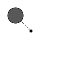 - Circular aperture (can be mirrored for a pair of apertures).
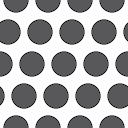 - Grid of circular apertures
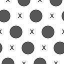 - Grid of circular apertures, excluding the transmitted beam,
as well as every 2nd lattice location. Especially useful when interrogating
superlattice reflections, whilst ignoring Bragg reflections from the matrix.
- Grid of circular apertures, excluding the transmitted beam,
as well as every 2nd lattice location. Especially useful when interrogating
superlattice reflections, whilst ignoring Bragg reflections from the matrix. - Bandpass mask.
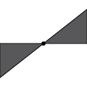 - Wedge mask extending from the transmitted beam to the edges of the
diffraction pattern. Default is mirrored across the transmitted beam;
however, this can be turned off to only capture scattering on one side of
diffraction space.
- Wedge mask extending from the transmitted beam to the edges of the
diffraction pattern. Default is mirrored across the transmitted beam;
however, this can be turned off to only capture scattering on one side of
diffraction space.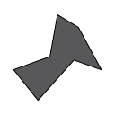 - User-drawn polygon shaped diffraction mask.
 - Import a mask image from file.
In the detector mask table, each mask has attributes listed as described below:
ID : A letter-based ID used in the software for addressing each mask.
Type : Mask class (
Circle,Grid,GridNoCenter,Bandpass,Wedge,Polygon,File)Label : User-defined label for easy data-specific context.
✅ : Enable/disable mask (disabled mask annotations are hidden).
👁 : Show/hide mask annotation (does not affect enable/disable state).
μ : Mask weighting (default = 1; limits = (-Inf, Inf))
Tip: to use the pre-defined detector masks centered on a different region of diffraction space, return to Alignment mode and shift the position of the transmitted beam annotation to be centered on the intended region of interest. Now all custom detector masks will be centered on the newly updated “transmitted beam” center.
Detector mask interactions
The user can add as many instances of a detector type as they wish. Because of this, the interaction between masks must be defined, both at the inter- and intra-mask level.
Inter-mask
This controls the interaction between all enabled detector masks.
Color Mix: Images generated from each detector mask are added together with their automatically assigned color, which can also be changed by the user. (Default)
Union: Logical or operation across all enabled detector masks. Resultant mask is binary 0 or 1.
Intersection: Logical and operation across all enabled detector masks. Resultant mask is binary 0 or 1.
Additive: Similar to Color Mix; however, detector masks are added before image generation, thus individual component images are less obvious in the final resultant image. Additive overlap between detector masks can result in significant weighting in diffraction space.
Current only: Only generate an image using the currently selected detector mask, irrespective of other enabled detector masks.
Intra-mask
Similar to inter-mask operations, some detector masks can result in overlapping components, requiring well-defined behavior.
Union: Logical or operation for all components within the selected mask. Resultant mask is binary 0 or 1. (Default)
Intersection: Logical and operation for all components within the selected mask. Resultant mask is binary 0 or 1.
Additive: Any overlapping components within the selected mask will be added, resulting in increased weighting in those regions of diffraction space.
Mask-specific options
Several mask transformation options exist depending on the specifics of the selected mask geometry. Not all options are available at all times.
 - mirror the mask across the transmitted beam.
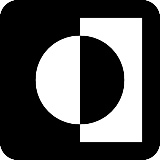 - invert the mask ([True, False] -> [False, True]).
 - change mask display color.
 ,
,  - rotate mask by angle in the dropdown.
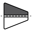 - mirror the mask across the horizontal plane ([x, y] -> [x, -y]).
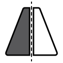 - mirror the mask across the vertical plane ([x, y] -> [-x, y]).
 - transpose the mask ([x, y] -> [y, x])
Mask maths
Watch this space.